
English
Views: 0 Author: Site Editor Publish Time: 2026-07-14 Origin: Site


A ground rod beside the concrete pad does not, by itself, make a transformer grounding system safe. The real challenge is coordinating the electrode system, enclosure bonds, neutral connection, cable shields, and surge protection so fault current has a controlled path and dangerous voltage differences do not develop. Because medium-voltage equipment must be handled by qualified personnel under proper de-energization procedures, the design should be confirmed before field connections begin.
The sections below focus on practical planning, correct bonding, performance testing, and the mistakes most likely to compromise a pad mounted transformer.
First determine whether the pad-mounted transformer belongs to the utility, the customer, or a private distribution operator. Ownership defines who approves the pad, grounding loop, primary terminations, test records, and energization. Obtain the serving utility’s current construction requirements before excavation because they may be more specific than general electrical rules. Resolve conflicts among utility, civil, electrical, and transformer documents before work begins.
The service boundary also affects how the transformer grounding system connects to the facility grounding electrode system. Record the party responsible for primary work, secondary work, inspection, testing, and final acceptance. A grounding arrangement approved for customer-owned equipment may not match the standard used by the serving utility. Field personnel should never be expected to select a neutral-bonding point from visual inspection alone.
Review the one-line diagram, nameplate, connection drawing, protection study, and installation instructions as one package. Identify primary and secondary voltages, vector group, X0 or neutral availability, radial- or loop-feed arrangement, and available ground-fault current. A grounded-wye secondary, an ungrounded system, and an impedance-grounded system do not follow the same neutral-bonding logic. The drawings must therefore define the system bonding jumper, grounding electrode conductor, and equipment grounding paths instead of leaving those decisions to the field crew.
Concentric neutrals, shields, elbows, arresters, and switching components introduce additional grounding points inside the cabinet. The conductive path should remain traceable from each normally non-current-carrying metal part back to the source. Grounding, high- and low-voltage connections, pre-energization checks, maintenance, and field acceptance testing must be treated as one coordinated installation process.
Pad-mounted transformer kVA does not independently determine rod quantity, electrode spacing, or an acceptable resistance value. Capacity affects the design indirectly through conductor size, fault duty, protection settings, and load type. A 5000kVA 12.47kV/690V three-phase JSYW transformer differs substantially from a 3150kVA, 25kV unit with a 415Y/240V secondary and Dyn1 connection. These differences show why the actual nameplate and connection drawing must guide grounding decisions.
Feed arrangement also changes the primary compartment. A radial-feed unit normally has one primary supply path, whereas loop-feed equipment accommodates additional cable and switching arrangements. Cable shields, elbows, parking stands, and switching components must correspond to the configuration selected for the project. The grounding details must match the equipment that is actually delivered.
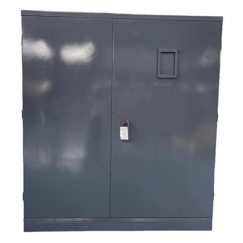
Electrode selection begins with the site rather than a preferred hardware list. Driven rods may suit deep, favorable soil; a buried ring or horizontal conductor may be more practical in shallow or rocky ground; and a grid can improve potential control where fault duty or personnel exposure is significant. Other qualifying site electrodes may also be bonded into the coordinated system. The design may combine several electrode types rather than relying on one method.
Soil resistivity, moisture, seasonal drying, frost depth, corrosion, available space, and buried utilities influence the arrangement. Adding closely grouped rods may provide less improvement than expected because their effective resistance areas can overlap. The pad-mounted transformer electrode should normally join the wider site grounding electrode system rather than remain isolated. Required test points and key connections must remain accessible.
Earth resistivity, grounding-system impedance, surface potential, and grounding-system integrity should be evaluated using suitable test methods. These measurements allow the electrode arrangement to reflect actual site conditions rather than assumptions about soil performance.
Ground resistance alone does not establish personnel safety. Touch voltage is the potential difference a person may bridge between the cabinet and the surface underfoot; step voltage is the difference between two points on the ground separated by a stride. During a fault, current entering the soil creates a voltage gradient around the electrode system. Ground rings, grids, bonded metalwork, engineered surface layers, and controlled access can reduce exposure by making the local potential more uniform.
Crushed rock or another specified surface layer may help at publicly accessible sites, but it cannot correct a missing bond or inadequate grid. The evaluation should consider fault current, clearing time, soil characteristics, electrode geometry, and surface conditions together. Touch and step voltage testing should also account for instrument limitations, probe placement, nearby grounding systems, and other conditions that may distort the results.
Site Condition | Likely Design Response | Main Issue to Verify |
Moist, lower-resistivity soil | Rods or a bonded ring may be practical | Seasonal variation |
Dry or sandy soil | Deeper or additional electrodes may be needed | Spacing and moisture changes |
Shallow rocky ground | Horizontal conductors or an engineered grid | Excavation limits |
Publicly accessible area | Equipotential grid and surface treatment | Step and touch voltage |
Corrosive environment | Compatible metals and protected joints | Long-term continuity |
Locate the pad-mounted transformer’s grounding pads, terminals, or internal ground bar before routing conductors. Bond the tank and cabinet to the site system with the conductor specified in the approved design. Doors, removable panels, barriers, support frames, metallic conduits, structural steel, or nearby fencing may need separate bonding where reliable continuity is not otherwise ensured. Painted hinges, mounting bolts, and contact with the concrete pad should not be assumed to provide an effective electrical path.
Keep bonding conductors direct, mechanically protected, and clear of operating components. Avoid unnecessary bends, especially on surge-related connections. Use listed connectors compatible with the conductor material and outdoor environment, prepare contact surfaces, apply specified joint compounds, and record torque values. Those records allow connection quality to be checked during inspection and future maintenance.
The equipment grounding network must connect normally non-current-carrying metal parts into an effective ground-fault current path. That path should be intentionally constructed with sufficiently low impedance to carry fault current back to the electrical source and support rapid operation of protective equipment.
Identify the secondary neutral or X0 terminal from the connection diagram. For a grounded separately derived system, the system bonding jumper connects the grounded conductor to the equipment grounding path at the approved point. Depending on the governing design, that point may be at the transformer or at an approved location associated with the first disconnecting means. It should not be duplicated at several points simply because multiple enclosures contain neutral bars.
A second unintended bond can place normal neutral current on raceways, enclosures, grounding conductors, cable shields, or other parallel paths. Downstream neutrals must remain isolated from equipment grounding conductors after the designated bonding point. Size the grounding electrode conductor and bonding jumper from the applicable electrical requirements and system data, not from a universal recommendation such as “always use No. 2 copper.” Confirm that shipping links or field jumpers have not created a parallel bond.
The system bonding jumper forms the connection between the grounded circuit conductor and the equipment grounding or supply-side bonding path at a separately derived system. Its position must therefore be established by the electrical design rather than repeated wherever a convenient connection point is available.
Connect concentric neutrals, cable shields, grounding elbows, termination points, and parking stands according to the utility and cable design. Surge arresters need short, direct grounding connections that minimize unnecessary impedance and limit the transient voltage imposed on protected medium-voltage cables. Arresters and their connecting conductors must suit the cable insulation level, system voltage, grounding arrangement, and expected surge conditions.
Radial-feed and loop-feed layouts change cable quantities, termination positions, switching components, and shield connections, but both require a continuous bonding network across the enclosure. Check raceways, cable trays, supports, and fencing that enter the grounding zone. Use approved transition hardware where dissimilar metals meet, and protect outdoor joints from moisture, chemicals, soil contact, and movement. Before closing the cabinet, ensure no grounding conductor obstructs an elbow, fuse, switch, barrier, drain path, or door mechanism.
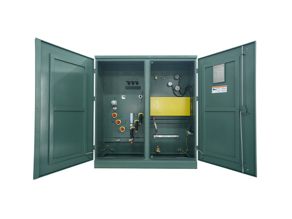
Compare the completed work with the approved pad-mounted transformer drawings before any resistance measurement begins. Trace the grounding electrode conductor, tank and door bonds, neutral connection, cable-shield grounds, arrester leads, conduit bonds, and every accessible joint. Confirm conductor sizes, connector listings, surface preparation, corrosion protection, and torque records. Where required, use a low-resistance continuity test to demonstrate that the metallic network is electrically intact.
Search specifically for unintended neutral-to-ground connections downstream of the designated point. Inspect compartments for loose strands, unsupported conductors, excessive bends, and leads that interfere with primary or secondary equipment. Photograph buried joints, electrode intersections, and concealed routes before backfilling so later changes can be investigated against a reliable baseline. Complete all pre-energization checks and field acceptance procedures together with the project inspection documents.
The test method must fit the system and the site. Testing may include earth resistivity, ground resistance or impedance, touch and step voltage, grounding-system integrity, instrument limitations, and conditions that may distort measurements. The fall-of-potential method is commonly used where probe placement is practical, while clamp-on testing depends on an appropriate interconnected return path and is not suitable for every new installation.
Do not treat 5 ohms or 25 ohms as a universal definition of a safe pad mounted transformer ground. Compare results with the engineered criteria, utility specification, adopted code, and authority having jurisdiction. When a result is unacceptable, first verify probe placement, lead routing, instrument condition, and possible interference. Inspect the connections, review electrode geometry, implement an approved correction, and then repeat the test under documented conditions.
The most serious error is relying on earth as the primary path for clearing a fault. Protective operation depends on the intentionally constructed conductive path formed by bonding and equipment grounding conductors. An isolated electrode can create potential differences between nearby systems, while multiple neutral bonds can place normal current on metalwork. Missing shield or arrester connections may also leave termination components exposed to hazardous voltage during faults or surges.
Installation Error | Likely Consequence | Correct Approach |
Isolated transformer electrode | Potential difference between grounding systems | Bond it into the coordinated site system |
Multiple neutral-ground bonds | Current on normally non-current-carrying metal | Use the designated bonding point |
Conductor selected by habit | Inadequate fault duty or noncompliance | Size from approved system data |
Incompatible metals | Corrosion and rising joint resistance | Use compatible or transition hardware |
Joint buried before testing | Defects become difficult to locate | Inspect, test, and document first |
Commissioning results provide the baseline for future maintenance. Inspect exposed conductors, clamps, bonding jumpers, cabinet grounds, and transition points for corrosion, loosening, overheating, damage, or unauthorized alterations. Retest after a major fault, lightning event, flooding, excavation, pad repair, cable replacement, or expansion of the surrounding system. Compare new readings with the original method and conditions rather than treating each number in isolation.
Maintenance frequency should reflect soil aggressiveness, weather, public access, utility rules, load criticality, and site history. Keep updated drawings, photographs, test reports, repairs, and conductor changes with the pad-mounted transformer record. Periodic integrity testing can identify broken conductors, deteriorated joints, corrosion, and changes in soil performance before they develop into a serious safety problem. Good records make deterioration easier to identify and correct.
Grounding a pad mounted transformer safely depends on the entire current path, not on a single ground rod. The electrode system, enclosure bonds, neutral connection, cable shields, surge arresters, and final test results must all match the approved electrical design and site conditions.
Jiangsu Yawei Electric Group Co., Ltd. provides pad-mounted transformer products and technical support for project planning, installation coordination, and commissioning. Selecting equipment around the required voltage, capacity, feed arrangement, and operating environment can reduce field changes while making future inspection and maintenance easier to manage.
A: Bond the tank, cabinet, required neutral point, cable shields, and surge arresters to an engineered grounding electrode system that follows approved drawings and utility requirements.
A: Not necessarily. A rod connects the system to earth, but fault clearing also requires a continuous, low-impedance metallic bonding path back to the electrical source.
A: No single value applies to every installation. Acceptance should follow the engineered design, utility requirements, soil conditions, step-and-touch limits, and applicable testing criteria.
A: Install it at the approved single bonding point, typically the transformer or first disconnect. Duplicate downstream bonds may place normal neutral current on conductive metalwork.
A: Common checks include visual inspection, bonding-continuity testing, and ground resistance or impedance measurement. Accessible sites may also require step-and-touch voltage testing.
A: Qualified electrical personnel should perform the work using approved de-energization, lockout, testing, and utility procedures appropriate for medium-voltage equipment.


