
English
Views: 0 Author: Site Editor Publish Time: 2026-07-27 Origin: Site


Data centers and commercial districts may rely on the same basic type of outdoor transformer, but they do not place the same demands on it. One must support concentrated, continuous loads and tight power-quality expectations; the other must serve changing tenant demand, multiple buildings, and phased expansion. As data-center electricity use and broader distribution-transformer demand continue to rise, selecting a pad mounted transformer by kVA alone is increasingly risky.
The right decision also depends on voltage, impedance, feeder layout, redundancy, site access, and future growth. Understanding these factors helps project teams avoid mismatched capacity, difficult installation, and costly changes after procurement.
A data center commonly receives underground medium-voltage power through service switchgear before a three-phase pad mounted transformer steps it down for low-voltage distribution. Power may then pass through UPS equipment and PDUs before reaching servers, storage, networking equipment, and cooling systems. Outdoor placement preserves indoor space for IT capacity, batteries, switchgear, and mechanical equipment. Three-phase pad-mounted units are generally applied in step-down service with underground primary cable supplies.
The pad mounted transformer is critical, but it is not a complete uptime solution. Continuity also depends on switchgear, buses, UPS systems, generators, controls, protective relays, and tested transfer sequences. A well-designed unit cannot remove a single point of failure elsewhere in the power path.
Commercial districts have more varied demand. Offices, shopping centers, hotels, and mixed-use buildings may peak at different times, while HVAC, elevators, food-service equipment, lighting, tenant electronics, and EV charging create distinct load profiles. Several pad mounted transformers can be positioned near separate load centers to shorten secondary runs and support phased development.
Placement is also more visible because equipment may sit near roads, parking areas, walkways, landscaping, or public entrances. Security, appearance, impact protection, and service access therefore carry greater weight than they may inside a controlled data center yard. Those constraints should be reflected in the site plan before cable routes are fixed.
Design Question | Data Center | Commercial District |
Primary concern | Continuity and capacity growth | Flexible service for mixed loads |
Load pattern | Concentrated and continuous | Diverse and time-dependent |
Expansion model | New IT halls or higher rack density | New buildings, tenants, or phases |
Power-quality focus | UPS interaction and voltage stability | Motor starting and load diversity |
Placement priority | Redundant routing and controlled access | Safety, accessibility, and low visual impact |
The comparison shows why one standard specification rarely suits both applications. Similar kVA ratings may still require different feeder layouts, loading assumptions, enclosure locations, and maintenance plans. The application context, not the enclosure alone, should drive the final design.
Pad mounted transformer sizing should start with a time-based load profile, not a sum of nameplate ratings. Connected load, diversified demand, expected operating load, peak demand, and reserved expansion capacity describe different conditions. Future allowance should be tied to a defined phase or growth scenario rather than an arbitrary percentage.
For a data center, the study should include present and planned IT demand, rack-density changes, UPS losses, cooling and pumping loads, and power transferred during maintenance or failure. Commercial districts require tenant diversity, occupancy schedules, seasonal HVAC peaks, elevators, motor starting, future fit-outs, new buildings, and charging infrastructure. Undersizing restricts growth and raises thermal stress, while excessive oversizing increases capital cost and leaves no-load losses running for years.
No-load losses occur whenever an energized transformer remains connected, even when the facility demand is low. Load losses increase as current rises and become more significant during sustained high-load operation. Evaluating both loss types helps project teams compare lifecycle performance rather than relying only on rated capacity.
The available utility voltage and required secondary voltage must be confirmed before pad mounted transformer selection. Secondary voltage affects switchgear, conductor current, downstream equipment, and the number of transformation stages. Grounding arrangement, winding connection, and tap range should appear on the one-line diagram before the RFQ is issued.
Impedance affects both voltage regulation and downstream fault current. Lower impedance can reduce voltage drop but permit higher fault current, while higher impedance limits current but increases voltage drop. The selected value must coordinate with switchgear ratings, cable ampacity, protection settings, motor starting, UPS behavior, and the short-circuit study.
A radial feed suits a straightforward single-source connection, while loop feed adds routing and switching options in an underground network. IEEE C57.12.34 covers applicable three-phase liquid-immersed pad-mounted transformers up to 10 MVA and includes terminal arrangements for radial- and loop-feed systems.
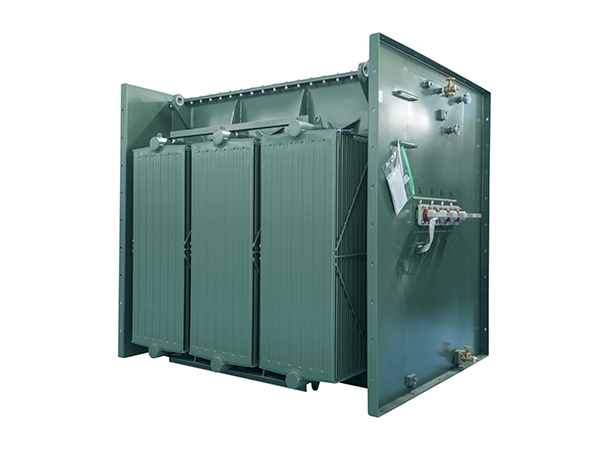
Available JSYW configurations include a 1500 kVA unit with a 12.47 kV primary and 208Y/120 V secondary, a 2500 kVA unit stepping 12.47 kV down to 600/347 V, and a 5000 kVA three-phase option with a 12.47 kV primary and 690 V secondary. The 1500 kVA configuration also uses outdoor installation, ONAN cooling, mineral oil, a 65°C temperature rise, and a tapping range of +2 × 2.5 percent.
These configurations illustrate different capacity and voltage requirements rather than automatic application matches. Final selection still depends on the load study, fault current, impedance, conductor design, redundancy plan, site conditions, and utility acceptance. The approved one-line diagram remains the controlling project document.
Redundancy describes the power architecture, not merely the pad mounted transformer count. N+1 adds one unit or path beyond the required quantity, while 2N duplicates the required capacity. Those labels only have value when switchgear, buses, controls, UPS systems, generators, protection, and cable routes support the same operating objective.
Parallel operation adds further requirements. Pad mounted transformers sharing load should have compatible voltage ratios, phase sequences, connection groups, tap positions, impedance values, and capacity ratios. Protection settings and load-sharing behavior must be studied before a tie is closed because mismatches can create circulating current or uneven loading.
Maintenance scenarios matter as much as failures. Operators should be able to isolate one unit, verify the switching sequence, and carry the remaining critical load without improvisation. Continuity is the result of coordinated equipment and tested procedures; no pad mounted transformer can guarantee zero downtime on its own.
UPS rectifiers, server power supplies, variable-frequency drives, LED drivers, charging systems, and tenant electronics can draw nonsinusoidal current. Harmonics may increase winding and conductor heating, affect neutral current, reduce usable transformer capability, and contribute to voltage distortion. IEEE C57.110 provides methods for evaluating transformer capability when supplying nonsinusoidal loads, including the effects of additional harmonic heating.
The correct response is not to specify a harmonic-related feature automatically. Engineers should identify the expected current spectrum, load mix, phase balance, grounding arrangement, and interaction with UPS or filtering equipment. The study may support transformer changes, filtering, conductor adjustments, load separation, or a combination of these measures.
Thermal duty also depends on average loading, ambient temperature, cooling method, and losses. Data centers may hold high loads for long periods, while commercial districts often show stronger daily and seasonal swings. Reviewing no-load loss, load loss, temperature rise, monitoring points, and expected duty cycle gives a better lifecycle picture than nameplate efficiency alone.
The pad mounted transformer location should be chosen while civil, architectural, and electrical routes remain flexible. Underground conduits, cable bending space, switchgear position, pad loading, drainage, flood level, and future expansion corridors all influence the final footprint. Data centers may require secured yards and separated feeder routes, while commercial districts must account for roads, storefronts, loading zones, landscaping, and pedestrian movement.
Delivery access should also be checked against actual dimensions and weight. The route must accommodate the transport vehicle, rigging plan, turning radius, overhead restrictions, and ground-bearing capacity. Installation planning should also address equipment handling, foundation preparation, grounding, electrical connections, pre-energization inspection, and field acceptance.
A pad mounted transformer near tenants or the public needs a secure enclosure and a site plan that discourages unauthorized contact. Enclosure integrity, locking provisions, compartment construction, grounding, barriers, and working access should be reviewed together wherever equipment energized above 600 V may be exposed to the public.
Vehicle exposure requires protection where parking stalls, roads, or delivery routes approach the transformer. Barriers must reduce impact risk without blocking doors, ventilation, cable access, or utility work space. Ambient temperature, rain, humidity, dust, salt exposure, altitude, and nearby noise-sensitive uses should be stated in the specification, while final clearances and fire separation must follow local utility and code requirements.
Maintenance access must survive landscaping changes and later development. Doors, cable compartments, radiators, and ventilation surfaces need permanent clearance. The site should preserve a route for inspection vehicles, oil-handling equipment where applicable, lifting machinery, and eventual transformer replacement.
Outdoor placement has limits. Sites with inadequate clearance, persistent flood exposure, restricted rigging access, or no safe maintenance zone may require another arrangement. Addressing these constraints during concept design is less disruptive than modifying utilities and hardscape after pad mounted transformer procurement.
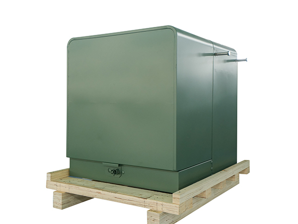
A useful RFQ should describe the electrical system, operating duty, and physical installation without requiring assumptions. Clear inputs reduce uncertainty during design review. The package should include:
● One-line diagram, operating and peak load, primary and secondary voltages, frequency, phase, grounding arrangement, available fault current, and required impedance.
● Radial- or loop-feed arrangement, winding connection, parallel-operation needs, tap range, insulation fluid, cooling method, temperature rise, and monitoring accessories.
● Site altitude and environment, applicable standards, cable-entry arrangement, dimensional limits, weight limits, and utility-specific requirements.
Complete information produces quotations that can be compared on the same technical basis. It also exposes conflicts early, such as an unsuitable secondary voltage, an impedance that misses fault-current objectives, or a cable compartment that cannot accept the planned terminations. IEEE C57.12.00 defines general requirements for liquid-immersed transformers, while IEEE C57.12.34 provides requirements for applicable pad-mounted configurations.
Pad mounted transformer testing requirements should be agreed before manufacturing. IEEE C57.12.90 includes test methods covering winding resistance, ratio, phase relation, losses, impedance, dielectric performance, temperature, short-circuit performance, and sound for applicable liquid-immersed transformers. The RFQ should identify routine test records and any project-specific witness or acceptance testing.
Delivery must align with pad completion, conduits, rigging access, switchgear readiness, cable termination, and protection settings. Before energization, the team should verify nameplate data, grounding, connections, fluid condition, accessories, protective devices, phasing, and approved settings. Data center commissioning should also test switching sequences across switchgear, UPS systems, generators, alarms, and monitoring systems.
A concise release checklist assigns responsibility. It should be reviewed before release and again before energization. Missing owners create avoidable project risk:
● Confirm the load study, voltage architecture, fault study, protection coordination, site plan, drawings, test records, delivery sequence, and commissioning owner.
● Record the normal configuration, contingency configuration, isolation method, switching authority, and maintenance procedure before turnover.
Selecting a pad mounted transformer for a data center or commercial district requires more than matching a kVA rating. Load behavior, voltage, impedance, redundancy, feeder design, site access, environmental exposure, and commissioning all influence long-term reliability and expansion flexibility.
Jiangsu Yawei Electric Group Co., Ltd. offers pad-mounted transformer configurations and project-specific technical support for medium-voltage distribution applications. By aligning capacity, secondary voltage, enclosure arrangement, and operating requirements with the actual site, its solutions can help project teams reduce design changes, simplify installation planning, and build a more maintainable power distribution system.
A: It steps underground medium-voltage power down to the voltage used by switchgear, UPS systems, HVAC equipment, lighting, and tenant loads. It is usually installed outdoors on a concrete pad.
A: Size should reflect operating demand, peak load, future expansion, power factor, cooling demand, and redundancy requirements. Connected equipment ratings alone can result in an oversized or undersized transformer.
A: Outdoor placement saves indoor space, supports underground distribution, and serves high-capacity three-phase loads. Reliability still depends on coordinated switchgear, UPS systems, generators, protection, and tested transfer sequences.
A: A radial feed has one primary supply path, while a loop feed allows alternative cable routing and switching. The choice depends on utility design, maintenance needs, and required system flexibility.
A: Yes, when properly specified and installed. Secure compartments, grounding, required clearances, vehicle barriers, drainage, and controlled maintenance access are essential in areas open to tenants or visitors.
A: Inspection frequency depends on loading, environment, utility rules, and manufacturer instructions. Typical checks include fluid condition, temperatures, connections, grounding, enclosure condition, protective devices, leakage, and corrosion.


