
English
Views: 0 Author: Site Editor Publish Time: 2026-07-01 Origin: Site


Those locked green or gray cabinets found beside homes, shopping centers, and industrial sites are not simple utility boxes. Each is typically a pad mounted transformer that receives medium-voltage electricity through underground cables and converts it into a usable voltage for nearby buildings or equipment.
Understanding what happens inside the enclosure helps explain why these transformers are used, how single-phase and three-phase designs differ, and what separates radial-feed from loop-feed configurations. It also makes it easier to evaluate applications, internal components, installation conditions, and basic safety requirements.
Electricity normally reaches a pad mounted transformer through a medium-voltage primary cable routed below ground. The cable connects to the high-voltage side through insulated bushings or cable interfaces inside the locked compartment. Alternating current in the primary winding produces a changing magnetic field in the core, which induces a new voltage in the secondary winding according to the turns ratio.
The transformer changes voltage; it does not generate electricity. Most distribution applications reduce the incoming voltage for residential, commercial, or light-industrial use. Residential systems may need single-phase service, while larger sites often require three-phase voltage for motors, HVAC equipment, and switchboards. Distribution transformers perform this final conversion between the primary circuit and customer-use voltage.
Current then leaves through the low-voltage terminals and secondary cables. One pad mounted transformer may feed a building, several homes, a local switchboard, or another part of a site network. The voltage ratio, capacity, phase, and protection scheme must match the connected system rather than the cabinet’s appearance.
Underground primary cable → Primary winding → Magnetic core → Secondary winding → Secondary cable → Building or equipment
The pad forms a stable, level base while aligning the cabinet with conduits and cable openings below. A suitable foundation also supports grounding, anchoring, drainage, and the clearances needed for installation and service. Because cables enter from underneath, the pad mounted transformer connects naturally to underground distribution without exposed overhead conductors at that location.
Ground-level installation is useful where poles conflict with site plans or appearance goals. It also lets authorized crews reach terminations, switches, and indicators without elevated work. JSYW provides enclosed single-phase and three-phase units for outdoor distribution nodes, residential complexes, commercial estates, and industrial sites.
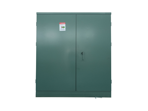
At the center of a pad mounted transformer are the magnetic core and primary and secondary windings. The core provides a path for magnetic flux, while the winding ratio determines the voltage change. Conductor selection, insulation, core geometry, and assembly quality influence efficiency, temperature rise, sound, and reliability. In an oil-immersed design, these active parts sit inside a sealed steel tank.
Insulating fluid provides dielectric separation between energized components and grounded surfaces. It also transfers heat from the core and windings toward the tank walls or cooling surfaces. Fluid type, fill level, sealing quality, and thermal design therefore affect both insulation integrity and operating temperature. This combination of insulation and cooling helps the transformer operate safely under changing load conditions.
Losses matter because the unit may remain energized continuously. No-load losses occur mainly in the core whenever the pad mounted transformer is energized, even when demand is low. Load losses arise largely in the windings and increase as current rises. Low-loss construction can reduce lifetime energy waste, but the correct design still depends on the expected load profile and applicable efficiency requirements.
The cabinet keeps medium-voltage input connections and low-voltage output connections organized and controlled. Primary bushings and separable cable connectors form the interface with the underground feeder, while secondary terminals connect outgoing conductors. Physical separation helps qualified technicians identify circuits, inspect terminations, and manage cable routing.
A tap changer may adjust the winding ratio within a limited range so delivered voltage better matches system conditions. Grounding points bond the enclosure and designated circuit components to the site grounding system. These features help integrate the pad mounted transformer into the utility or facility network, but they do not replace correct system studies and approved connection drawings.
A pad mounted transformer may combine voltage conversion with switching and protection in one cabinet. Load-break switches let authorized operators isolate or reconfigure primary circuits where the network design allows it. Fuses respond to abnormal current, while surge-protection devices may limit transient overvoltage.
The sealed tank also needs mechanical safeguards. A pressure-relief device provides a controlled response to excessive internal pressure, and oil-level, temperature, or pressure indicators support condition checks. JSYW designs integrate the core, windings, protective devices, corrosion-resistant enclosure, moisture-control details, thermal management, secure bushing interfaces, and pressure relief into a compact outdoor unit.
Phase configuration must match the source circuit and connected loads. A single-phase pad mounted transformer commonly serves residential clusters, rural branches, and smaller commercial loads. It is appropriate where the network does not need three-phase motors or a large balanced three-phase supply.
Three-phase units suit commercial properties, industrial facilities, campuses, infrastructure projects, and larger developments. They can feed large HVAC systems, pumps, production machinery, and three-phase switchboards. Three-phase is not automatically better; it is correct only when it matches the available primary system, required secondary voltage, and load profile.
JSYW’s product range covers different distribution duties. The ZGD-H-100 is a 100 kVA single-phase pad mounted transformer intended for residential, commercial, and light-industrial distribution, while the 5 MVA three-phase oil-immersed unit supports substantially larger loads. The 100 kVA configuration can be supplied with a 12.47 kV grounded-wye primary and a 240/120 V secondary, although final ratings must always be confirmed against the project specification.
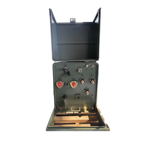
Feed arrangement determines whether the primary cable terminates at the transformer or continues through its location. A radial-feed pad mounted transformer has one primary supply path and suits simpler branches or end-of-line points. Its straightforward layout can reduce circuit complexity where through-feed switching is unnecessary.
A loop-feed unit allows the primary circuit to enter and continue onward. Depending on the switch configuration and wider network, operators may isolate a faulted cable section or resupply healthy sections from another direction. This improves operating flexibility, but loop feed alone does not guarantee uninterrupted power. Feeder layout, alternate sources, protection, cable condition, and switching procedures also affect service continuity.
Phase, feed, and connection style are separate choices. Single-phase and three-phase units may use radial or loop arrangements when their designs permit. Dead-front or live-front interfaces are selected according to utility practice, cable systems, access control, and safety requirements.
Selection factor | Option | Generally suited to |
Phase arrangement | Single-phase | Residential and smaller localized loads |
Phase arrangement | Three-phase | Commercial, industrial, and higher-capacity loads |
Primary circuit | Radial feed | Simpler branches or terminal points |
Primary circuit | Loop feed | Networks needing through-feed flexibility |
Connection design | Dead-front | Insulated connection systems in accessible locations |
Connection design | Live-front | Controlled sites built to the required utility specification |
The clearest use case is an underground system that needs voltage conversion near the load. Residential subdivisions use pad mounted transformers to supply groups of homes without placing pole equipment along each street. Apartment developments, offices, retail centers, hotels, schools, and healthcare campuses use them where a secure outdoor distribution point fits the electrical plan.
Industrial estates may use larger three-phase units to feed production buildings, motor loads, or central switchgear. Solar plants, battery-storage installations, and other grid-connected projects can also require a transformer between equipment voltage and the distribution network. The direction of transformation and protection scheme must match the project rather than being assumed from the enclosure.
Externally similar cabinets may differ greatly in kVA, voltage, impedance, phase, feed arrangement, fluid, losses, and accessories. JSYW provides single-phase and three-phase pad mounted transformer designs, including higher-capacity oil-immersed products. Procurement teams should therefore evaluate the nameplate and technical schedule instead of judging capability by cabinet size.
A pad mounted transformer sits at ground level and normally connects to underground cables. A pole-mounted unit is elevated and usually integrated with overhead lines. The ground-level format encloses connections in a locked cabinet, while pole equipment is arranged for elevated utility access.
Neither installation is universally superior. Underground systems reduce visible overhead infrastructure but require trenching, conduits, foundations, drainage, and ground space. Pole-mounted systems avoid the same equipment footprint but depend on poles and overhead conductors.
The choice is made at the distribution-system level. Cable routing, utility standards, service density, capacity, civil cost, maintenance strategy, and environmental exposure all influence the result. Both formats can reduce primary distribution voltage to customer-use levels, but they require different cable systems, site preparation, access arrangements, and maintenance methods.
Transformer selection and civil design should be coordinated from the start. Engineers confirm primary and secondary voltage, phase, capacity, load profile, motor starting, future growth, impedance, and protection. These decisions affect cable size, conduit count, termination space, pad openings, dimensions, and available fault current.
Site planning must account for foundation strength, anchoring, grounding, drainage, flood exposure, ventilation, and heat dissipation. Access routes should allow delivery or replacement equipment to reach the pad mounted transformer. Vehicle barriers may be required, but they cannot obstruct doors or working space.
Clearance values should follow the serving utility’s requirements, applicable codes, manufacturer drawings, and approved project documents. Required distances can vary between utilities and projects. Dense landscaping, fences, walls, stored materials, and other obstructions must not block cabinet doors, ventilation areas, or maintenance access.
A pad mounted transformer contains high-voltage equipment and should not be treated as seating, storage, or a landscaping feature. Only qualified, authorized personnel should open the cabinet or work on internal circuits. Anyone working on energized equipment must understand its operation, electrical hazards, isolation procedures, and required protective measures.
External warning signs can still be recognized without opening the enclosure. Oil leakage, severe corrosion, damaged doors, broken locks, unusual noise, overheating, flooding, soil movement, impact damage, or blocked ventilation should be reported to the responsible utility or facility team. Clear space in front of the doors allows crews to inspect, switch, test, or replace the equipment.
Professional upkeep may include visual inspection, thermal scanning, checks of bushings and terminations, grounding verification, switch and fuse assessment, fluid sampling, and leak inspection. Frequency depends on age, loading, environment, operating history, manufacturer guidance, and the owner’s maintenance program.
Before specifying a unit, confirm:
● Required kVA and future demand
● Primary and secondary voltage
● Single-phase or three-phase service
● Radial or loop-feed arrangement
● Ambient, flood, corrosion, and access conditions
● Utility connection and clearance requirements
● Protection, switching, monitoring, and fluid requirements
A pad mounted transformer combines voltage conversion, underground cable connections, switching, and protection within a secure ground-level enclosure. Choosing the right unit requires more than matching capacity: phase configuration, primary and secondary voltage, feed arrangement, load profile, site access, and environmental conditions must work together. Jiangsu Yawei Electric Group Co., Ltd. provides single-phase and three-phase pad mounted transformer options for residential, commercial, industrial, and utility distribution needs, helping project teams match transformer design and technical support with practical installation and long-term operating requirements.
A: It receives medium-voltage electricity from underground distribution cables and converts it into a lower voltage suitable for nearby homes, commercial buildings, or industrial equipment.
A: Ground-level placement supports underground cable entry, secure public-area installation, and easier access for qualified utility personnel during inspection, maintenance, switching, or outage restoration.
A: Properly installed units enclose energized parts inside a grounded, locked cabinet. People should avoid touching, climbing on, damaging, or obstructing the transformer.
A: Required clearance varies by utility, transformer design, and local codes. The installation must preserve door operation, ventilation, maintenance access, and safe separation from obstructions.
A: Pad-mounted units sit in locked ground-level cabinets and usually connect to underground cables, while pole-mounted transformers are elevated and normally serve overhead distribution systems.
A: Typical components include the magnetic core, windings, insulating fluid, primary bushings, secondary terminals, fuses, switches, grounding connections, and basic pressure or temperature indicators.


